External Gauge Control
Blown Film Extrusion
Reduce Film Thickness Variations by 50+%
The patented EGC system stands out among all other air ring based systems through the number of control zones, 132-244, depending on the air ring size. This high number enables the system to address film thickness
variations that other systems cannot. The EGC incorporates the well known Addex air ring that assures the highest possible output. Now available on rotating dies!
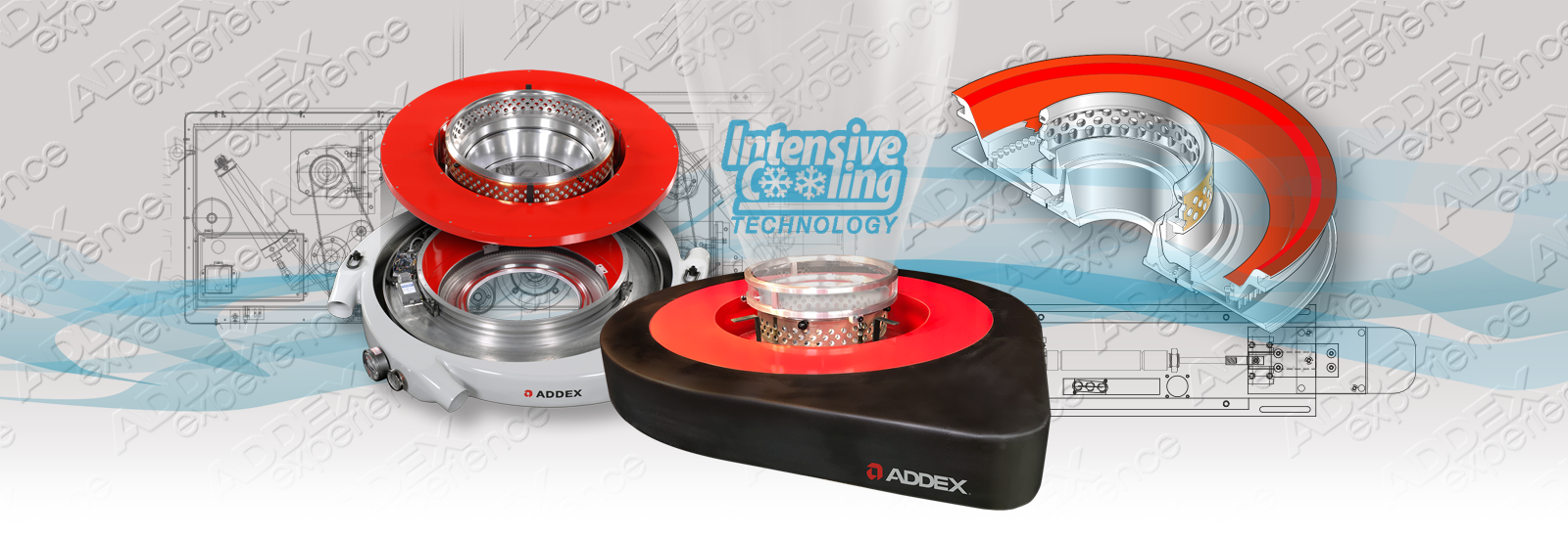
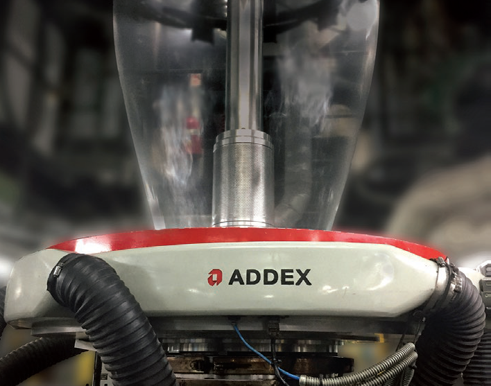
The Air Ring
The air ring is equipped with horizontally sliding teeth that adjust the air flow through the radially located vanes in the air ring’s plenum causing preferential cooling on the outside of the bubble.
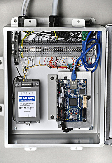
A circuit board inside the air ring converts the mapped thickness profile into instructions for the scanning actuator which slides “in” or “out” a multitude of fingers (132-244 depending on air ring
size), as needed, to open or close the airflow channels (vanes).
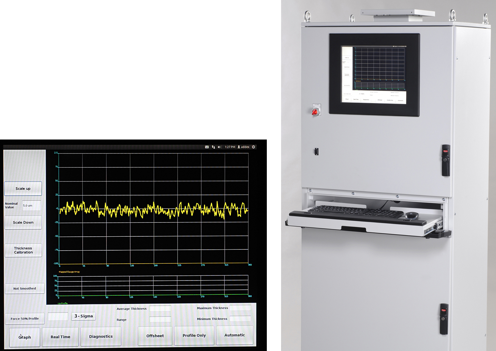
The Mapper
The Mapper Processes the raw signal profile and the reversing or fully-rotating nip position and nip roll speed.
Specs
| Size | Diameter | Number of Air Inlets | Number of Control Zones |
|---|---|---|---|
| 4"–8" | 100–200 mm | 48" | 1220 mm 6 x 4"/102 mm | 90-144 |
| 8"–16" | 200–400 mm | 56" | 1423 mm 6 x 4"/102 mm | 120-168 |
| 16"–24" | 400–600 mm | 64" | 1626 mm 8 x 4"/102 mm | 168-216 |
| 37"– 40" |925–1000 mm | 76" | 1931 mm 10 x 4"/102 mm | 224-288 |
Larger ones are available upon request.
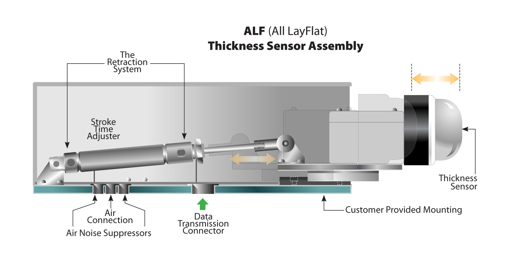
Sensor Location Options
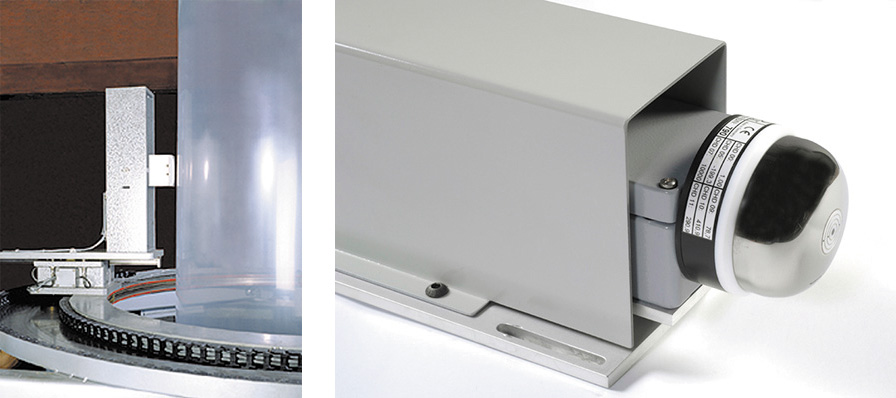
Thickness Sensor Options
Floor-Mounted Console | Graphical User Interface Displays
Air Requirements
| US | METRIC | LEGEND: |
|---|---|---|
| D" x 150 = CFM | D mm x 10 = m3/h | D"= Die diameter in inches |
| @ 80ºF & 25"H2O | @ 27ºC & 6.2 KPa | D mm = Die diameter in mm |
| CFM = Cubic feet per minute | ||
| F = Degrees Fahrenheit | ||
| C = Degrees Celsius |